Free Cad Get Sketch Straight Again
| |
| Topic |
|---|
| Sketcher |
| Level |
| Beginner |
| Time to complete |
| 60 minutes |
| Authors |
| Drei and vocx |
| FreeCAD version |
| 0.19 |
| Instance files |
| Basic Sketcher tutorial updated |
| |
Introduction
This tutorial was originally written by Drei, and information technology was rewritten and illustrated by vocx.
This tutorial is meant to innovate the reader to the basic workflow of the ![]() Sketcher Workbench.
Sketcher Workbench.
The Sketcher Workbench exists as a standalone module, so information technology tin exist used to describe generic 2d (planar) objects. Still, it is mostly used in conjunction with the ![]() PartDesign Workbench. A closed sketch is unremarkably used to create a face up or a profile to be extruded into a solid body with an operation such equally
PartDesign Workbench. A closed sketch is unremarkably used to create a face up or a profile to be extruded into a solid body with an operation such equally ![]() PartDesign Pad.
PartDesign Pad.
The reader will exercise:
- Creating construction geometry
- Creating real geometry
- Applying geometric constraints
- Applying datum constraints
- Obtaining a closed contour
For a more than in depth description of the sketcher, read the Sketcher reference.
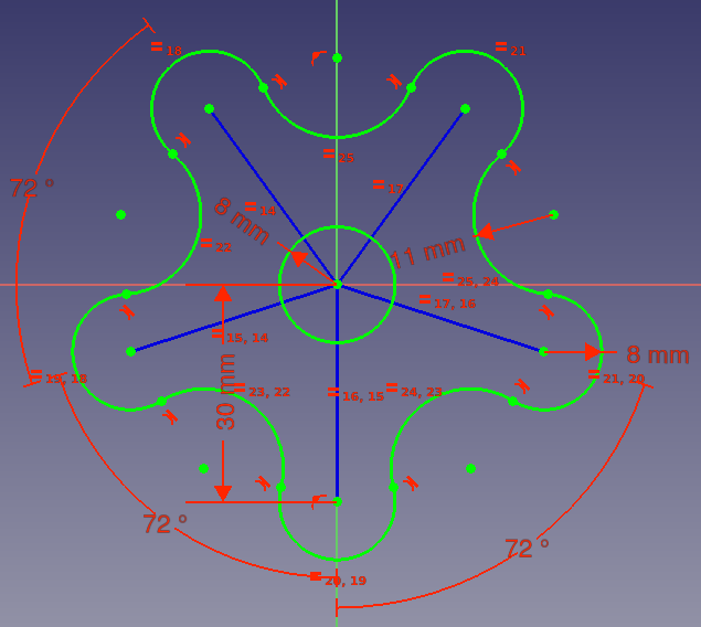
Final upshot of the sketch, with all geometry fully constrained, including construction geometry for support.
Setup
1. Open FreeCAD, create a new empty certificate with File → ![]() New.
New.
- 1.1. Switch to the Sketcher Workbench from the workbench selector, or the menu View → Workbench → Sketcher.
Some actions to call up:
- Press the right mouse button, or press Esc in the keyboard one time, to deselect the active tool in edit manner.
- To exit the sketch edit mode, press the Shut push in the task console, or press Esc twice in the keyboard.
- To enter again edit mode, double click on the sketch in the tree view, or select information technology, and then click on
 Edit sketch.
Create a sketch
two. Click on ![]() New sketch.
New sketch.
- 2.ane. Choose the sketch orientation, that is, one of the base of operations XY, XZ, or YZ planes. Besides choose if you want an inverted orientation, and an offset from the base aeroplane.
- two.2. Nosotros will use the default plane and options.
- ii.three. Click OK to start constructing the sketch.
We are now inside the sketch edit mode. Within it, nosotros're able to make use of the majority of the tools of this workbench.
Note: the tree view will switch to the job console; in this interface expand the Edit controls department, and make sure the Auto constraints option is enabled. Other options tin be inverse including the size of the visible grid, and whether we want to snap to it; in this tutorial we will non snap to the filigree and nosotros will also hide it. In other sections of the chore panel you can also meet which geometrical elements and constraints have been divers.

Upper part of the task console of the sketcher.
Construction geometry
3. Construction geometry is used to guide the creation of "existent" geometry. Real geometry will be the one shown exterior of the sketch edit mode, while structure geometry will only be shown inside the edit mode. Therefore, you can use as much structure geometry every bit you need to build real shapes.
- three.ane. Click on
 Toggle construction. Now geometrical elements will be drawn in Construction style.
 - 3.2. Click on
 Create line.
 - 3.three. Approach the origin of the sketch, the indicate should highlight and most your cursor the
 coincident constraint icon volition appear.
 - 3.iv. Click on the point, and then movement the pointer to first drawing a new line from it. Motility the arrow and so that the line has a length to around
30 mm. You lot don't have to exist very precise in this step; later nosotros will set the correct dimension. - iii.five. Repeat this process iv more times to place construction lines in a star pattern. Don't worry as well much nigh their size or position, just extend them in the four quadrants.
- 3.6. Now leave structure mode by clicking again on Toggle construction.
Note: up to this point the line tool is however active. This means we tin keep clicking on the 3D view to describe as many lines as we want. If nosotros wish to exit this tool, we tin can press the correct mouse push button, or press Esc in the keyboard one time. By doing this the arrow won't create lines any more, it will just be a arrow allowing united states of america to select the objects nosotros just created. In this pointer mode we tin can pick and drag the endpoints of each line to adapt its placement.
Note 2: exercise non press Esc a second time as this will get out the sketch edit mode. If you exercise this, re-enter the edit way by double clicking on the sketch in the tree view.
Take a look at the task console again. The Solver messages section already indicates that the sketch is nether-constrained, and information technology mentions the number of degrees of freedom.
Look at the Constraints and Elements sections to encounter the new listed constraints and lines. Once your sketches have many elements, it may be difficult to select them in the 3D view, so you lot can use these lists to select the object that y'all wish exactly.

Construction lines forming a star shape with its center in the origin.
Real geometry
Existent geometry must make a closed shape if information technology is to be used as a profile that tin be extruded past tools such as ![]() PartDesign Pad.
PartDesign Pad.
Brand sure you are non in structure style by clicking on ![]() Toggle construction, if yous have not previously exited this style.
Toggle construction, if yous have not previously exited this style.
Outer arcs
4. Create a circle.
- 4.1. Click on
 Create circumvolve.
 - 4.2. Click on the origin of the sketch to position its center point.
- four.iii. Click anywhere in the 3D view to set the circumference radius as a altitude from the origin. Make it approximately
8 mm. Again the dimension will be fixed subsequently.
5. Create a series of arcs.
- 5.1. Click on
 Create arc.
 - five.2. Approach the endpoint of 1 of the construction lines, and click on information technology. This will set the heart point of the circular arc to be coincident with this line's endpoint.
- 5.three. Click once in the 3D view at an capricious location to set simultaneously the radius of the arc, and the commencement endpoint of it. Define an approximate radius of
8 mm. - 5.4. Movement the pointer in an anti-clockwise direction to trace an arc that has its concavity pointing towards the origin of the sketch. Click to gear up the final endpoint of the arc, defining a circular arc that approximately sweeps
180°or one-half a circumvolve. - 5.v. Repeat these steps with each structure line, and then that each of them has a circular arc at its tip. Nosotros will call these O-arcs for outwards-arcs.

Circular arcs added at the endpoints of the construction lines. Also a fundamental circle.
Inner arcs
6. Create an arc between each pair of the previous O-arcs.
- half dozen.one. Nonetheless with the Create arc tool active, click somewhere between two O-arcs but further away from the origin of the sketch, to set the center point of a new arc.
- 6.2. Click somewhere shut to the endpoint of one O-arc, and move the pointer to sweep another arc finishing close to another endpoint of a different O-arc, as if you were trying to bring together the endpoints. This fourth dimension the concavity must point away from the origin.
- six.iii. Repeat these steps, so that each pair of O-arcs has a new arc between them. We will call these I-arcs for inwards-arcs.
To summarize, the O-arcs should have their curvature pointing outwards, and their concavity pointing towards the origin of the sketch; the I-arcs should have their curvature pointing inwards, and their concavity pointing away from the same origin.

Circular arcs added between the start set of arcs placed.
Constraints
Take a look at the task panel again. Due to the new geometrical elements that we have fatigued, the Solver letters section indicates fifty-fifty more degrees of freedom. A degree of freedom (DOF) indicates a possible movement of ane element. For case, a point can exist moved both in horizontal and vertical directions, so it has two degrees of freedom. A line is divers past two points, therefore in total information technology has iv degrees of freedom. If nosotros fix one of those points, so the unabridged system has simply two degrees of freedom available; if we additionally gear up the horizontal movement of the remaining point, we merely have one caste of freedom left; and if we too fix the vertical motility of this point, then the last degree of freedom disappears, and the line cannot move from its position whatsoever more.
Up to now when we have fatigued lines and curves, the sketcher has added automatic constraints for us, those that keep the lines tied to the origin, and the O-arcs tied to the structure lines. Merely we haven't added other explicit constraints so the geometrical shapes can nevertheless exist moved in many directions. Constraints are "rules" that tell us under which weather condition a geometrical object tin move and by how much. They are used to eliminate the degrees of freedom and then that the sketch has a stable shape. If nosotros eliminate all degrees of freedom, and so the sketch is fully constrained, and has a fixed shape, that is, its points cannot move at all. In full general, it is a good idea to fully constrain sketches because this volition event in stable models.
There are two principal types of constraints:
- Geometric constraints define characteristics of the shapes without specifying exact dimensions, for example, horizontality, verticality, parallelism, perpendicularity, and tangency.
- Datum constraints ascertain characteristics of the shapes by specifying dimensions, for case, a numeric length or an angle.
Geometric constraints
Equal length and radius
7. Geometrically constrain the lines and arcs.
- seven.ane Select all five construction lines. You lot only need to click once to select an chemical element.
- vii.2. Press
 Equal length.
 - Annotation: this creates only four constraints. The constraints are chained, the showtime line has the same length as the second one, which has the same length as the third 1, which again has the same length as the fourth ane, which has the aforementioned length equally the 5th one. And then in this case, the first and the fifth accept the same length.
- vii.three. Select all 5 O-arcs, those centered on an endpoint of a construction line.
- 7.4. Press Equal length.
- 7.v. Echo with all I-arcs, those between the O-arcs.
- Note: again the constraints are chained. Therefore all O-arcs will accept the same radius, and all I-arcs will have the same radius. At this moment, the specific value of these lengths is non fixed. You may use the pointer to drag a point and come across how the sketch is updated while respecting the constraints in place.
- vii.six. Select the construction line that is closest to the vertical axis.
- 7.7. Press
 Vertical (optional). If you drew the construction line downwardly over the Y axis, an automatic
  Signal on object constraint was already placed, keeping the construction line vertical. In this case, no additional Vertical constraint is necessary.
Note: as you add constraints, overlay symbols indicating the type of constraint appear over the geometry in the 3D view. If these symbols obfuscate your view, y'all can hide them past unchecking the constraint in the task panel. Also note that the number of degrees of liberty decreases after calculation each constraint.
Note 2: if yous wish to temporarily disable the constraint, you may select it and press ![]() Toggle agile constraint. When you desire to apply information technology again, press over again the same push.
Toggle agile constraint. When you desire to apply information technology again, press over again the same push.


Sketch with equality constraints applied to the construction lines, and to the two sets of arcs.
Tangency
8. Use tangency to the arcs.
- eight.i. Select 1 endpoint of an O-arc and then the closest endpoint of the adjacent I-arc.
- eight.2. Press
 Tangent. This makes the two next arcs connect smoothly at their endpoints.
 - 8.3. Repeat for all endpoints of the O-arcs and I-arcs to obtain a closed profile.
Annotation: applying the tangential constraint very ofttimes volition move the geometry effectually in lodge to produce a smooth connection. Yous may have to use the pointer to reposition the points a bit earlier applying the side by side tangential constraint. Try placing the endpoints in such a way that two arcs aren't as well far apart, then they can be connected with a short line rather than a long line.
As of this step, we have now created a closed profile, as all arcs have been tied together. Now nosotros tin can provide datum constraints to set up the shape of the sketch. While the dimensions of lines and arcs remain unfixed, we can elevate the points of the sketch and observe how the entire sketch changes.

Sketch with tangential constraints applied to the arcs, which closes the shape.
Datum constraints
These constraints specify the numerical distances between two points, and angles betwixt two lines.
Distances and angles
nine. Adjust the size of the construction lines.
- nine.1. Select the vertically constrained structure line.
- 9.2. Press
 Vertical distance.
 - ix.3. Set the length to
30 mm. Because all construction lines are constrained to take the same length, all these lines adjust their sizes at the same time.
10. Adjust the angle between the construction lines.
- 10.1. Select the vertical construction line and the construction line closest to information technology.
- 10.2. Press
 Angle.
 - 10.3. Prepare the angle to
72°. - x.4. Repeat the same procedure for each pair of structure lines, and use the same bending.
- Notation: at this stage, the sketch may take very few degrees of freedom left, significant that its shape cannot be changed likewise much. If you attempt to add together more constraints, these may cause a conflict with the previously added constraints. If this is the case, do non add these constraints, and proceed with the side by side steps.


Sketch with length constraint applied to one vertical structure line (left), and angle constraints to three pairs of structure lines (correct).
Radius
eleven. Suit the size of the arcs.
- 11.1. Select one of the O-arcs, centered on the endpoint of a construction line.
- 11.2. Press
 Radius.
 - 11.3. Set the radius to
eight mm. Because all O-arcs are constrained to have the aforementioned radius, all these arcs adjust their sizes at the same time. - xi.4. Select ane of the I-arcs, between ii O-arcs.
- 11.5. Printing Radius.
- 11.6. Set up the radius to
eleven mm. Because all I-arcs are constrained to accept the same radius, all these arcs adjust their sizes at the same time.


Sketch with radius constraints applied to the outwards arcs (left), and in arcs (right).
- 11.vii. Finally, select the circle in the eye of the sketch, press Radius, and set the value to
8 mm.
We should end up with a fully constrained sketch. Information technology can be confirmed by noticing the change in color of the real geometry, and by the bulletin that is shown in the task console.

Sketch with all geometrical and datum constraints applied.
Extrusion
12. Now that nosotros have a fully constrained sketch, it can be used to create a solid body.
- 12.i. Go out the sketch edit mode past pressing the Close button, or pressing Esc twice. The sketch should announced in the tree view and the 3D view.
- 12.two. Switch to the PartDesign Workbench.
- 12.iii. With the sketch selected in the tree view, press
 PartDesign Torso, choose the default XY-plane, and press OK. The sketch should appear now inside the Body.
 - 12.4. Select the sketch, so press
 PartDesign Pad, choose the default options, and printing OK to create a solid extrusion.


Left: fully constrained sketch with only the most important constraints showing. Right: solid extrusion produced with PartDesign Pad.
Boosted information
For a more in depth description of the sketcher, visit the Sketcher Workbench documentation and likewise read the Sketcher reference.
Constraining a sketch can be done in many dissimilar ways. In general, it is recommended to apply geometrical constraints first, and minimize the number of datum constraints, equally this simplifies the task of the internal constraint solver. To investigate this, repeat this instance, at present adding the constraints in different order.
- Outset constrain the construction lines before drawing the arcs.
- Or constrain the size of the arcs before making them tangent.
- Or set the angle of the construction lines before adding more than elements.
- Try using other construction geometry.
![]() Tutorials
Tutorials
- General: Tutorials, Video tutorials (Product pattern, Compages, Obsolete)
- Arch: Curvation tutorial, Open windows, Custom windows
- Typhoon: Typhoon tutorial, Traditional drafting
- Sketcher: Basic Sketcher tutorial, Sketcher reference
- PartDesign: Simple object, Simple object 2, How to use FreeCAD PartDesign
- Office: Engraved text, Wiffle ball, Basic modeling, Spiral threads, Placement
- TechDraw: Bones TechDraw tutorial, New template
- Path: Path for the impatient
- FEM: Cantilever analysis, Electrostatic analysis, Shear in a composite cake, Postprocessing with Paraview, Reinforced physical
- Rendering: Raytracing tutorial, POV-ray, Blender
- A2plus: Gripper assembly
- Assembly3: Test tutorial How to utilise Assembly 3
- Assembly4: Assembly4 tutorial
![]() Sketcher
Sketcher
- General: Create sketch, Edit sketch, Leave sketch, View sketch, View section, Map sketch to face, Reorient sketch, Validate sketch, Merge sketches, Mirror sketch, Stop operation
- Sketcher geometries: Point, Line, Arc, Arc by 3 points, Circle, Circle by 3 points, Ellipse, Ellipse by three points, Arc of ellipse, Arc of hyperbola, Arc of parabola, B-spline, Periodic B-pline, Polyline, Rectangle, Centered rectangle, Rounded rectangle, Triangle, Square, Pentagon, Hexagon, Heptagon, Octagon, Regular polygon, Slot, Fillet, Trim, Extend, Split, External geometry, Carbon copy, Toggle structure geometry
- Sketcher constraints:
- Geometric constraints: Coincident, Point on object, Vertical, Horizontal, Parallel, Perpendicular, Tangent, Equal, Symmetric, Block
- Dimensional constraints: Lock, Horizontal distance, Vertical distance, Distance, Radius, Diameter, Radiam, Angle, Snell'southward law, Internal alignment
- Constraint tools: Toggle driving/reference constraint, Activate/deactivate constraint
- Sketcher tools: Select unconstrained DoF, Shut shape, Connect edges, Select associated constraints, Select associated geometry, Select redundant constraints, Select conflicting constraints, Show/hide internal geometry, Select origin, Select vertical axis, Select horizontal centrality, Symmetry, Clone, Copy, Movement, Rectangular array, Remove axes alignment, Delete all geometry, Delete all constraints
- Sketcher B-spline tools: Show/hibernate B-spline caste, Show/hide B-spline control polygon, Show/hide B-spline curvature comb, Prove/hide B-spline knot multiplicity, Testify/hide B-spline control signal weight, Convert geometry to B-spline, Increase B-spline degree, Decrease B-spline degree, Increase knot multiplicity, Subtract knot multiplicity, Insert knot
- Sketcher virtual space: Switch virtual space
- Additional: Sketcher Dialog, Preferences, Sketcher scripting
![]() User documentation
User documentation
- Getting started
- Installation: Download, Windows, Linux, Mac, Additional components, Docker, AppImage, Ubuntu Snap
- Basics: About FreeCAD, Interface, Mouse navigation, Selection methods, Object name, Preferences, Workbenches, Certificate structure, Backdrop, Aid FreeCAD, Donate
- Help: Tutorials, Video tutorials
- Workbenches: Std Base, Arch, Draft, FEM, Paradigm, Inspection, Mesh, OpenSCAD, Part, PartDesign, Path, Points, Raytracing, Reverse Engineering, Sketcher, Spreadsheet, Showtime, Surface, TechDraw, Examination Framework, Web
- Deprecated or unmaintained workbenches: Complete, Drawing, Robot
- Addons: Addon Manager, External workbenches, Scripting and macros
- Hubs: User hub, Ability users hub, Developer hub
Source: https://wiki.freecadweb.org/Basic_Sketcher_Tutorial
0 Response to "Free Cad Get Sketch Straight Again"
Enregistrer un commentaire